Communication Protocols of Control System – Ryka Engineering Solutions
In an operating plant, more the operating process data it gives better monitoring and control of the processes and lead indicators resulting into minimal downtime. This has a direct relation of production volumes and yields improved financial results. Providing this running plant parameter feedback is performed with different instruments working on different technologies. This instrument not only communicates the plant data to the central control system but also provides the self-health status data. The field of industrial communications is continuously developing at astonishing pace to cater the needs of industry. It is evolved from pneumatical to electrical communications.The technological developments have enabled this industry move from digital communication to a wireless mode of communications.
This effort is towards addressing the communications and will briefly cover:
-
Communication basics
-
Serial communication and it’s basic standards
-
Communication protocols:
-
MODBUS
-
HART
-
DeviceNet
-
ASIbus
-
PROFIBUS
-
FOUNDATION FIELDBUS
-
Overall comparison of communication protocols
-
-
Wireless network
-
Engineering approach
-
Communication basics:
Have you ever experienced communicating with a person who did not know your language without help of an interpreter?
You must have experienced struggle to convey the message with some gestures, it must have created some funny situation.
In order to communicate to each other, the sender and receiver have to be agree on the “language or format” of communication.
A communication protocol is a system or set of rules or definite format that allow two or more entities to transmit/receive information. These are the rules or standard that defines the syntax, semantics and synchronization of communication and possible error recovery methods.
A communication protocol is a function of three nos.of important entities: Physical layer, Transmission media and Network topologies.
The physical layer of the communication defines how data are to be physically transported from device to device.
Transmission media means the cables used in the communication are the backbones of networks. There are three types of cables: twisted pairs cables, co-axial cables and glass fibre cables.
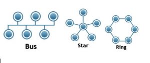
The network topology describes the way in which the devices in the network are connected together. The basic topologies are star, ring and bus arrangements, as shown below:
-
Serial communication and it’s basic standards:
Serial communication is the process of sequentially sending one bit of data at a time. This is two-way (full duplex) type communication. The transmission media of this communication is possible via only three separate wires as minimum- one to send, other to receive, and a common signal ground wire.
Basic Standards:
RS-232 is the oldest standard for serial communication transmission of data (RS stands for recommended standard). RS-232 is commonly used in computer serial ports.RS232 allows data transfer at relatively slow speed (up to 20K bits/sec) and short distances (up to 50 ft.). RS232 has limitation of slow speed, noise and non-detection of error.
RS-485 is next commonly used standard for serial communication transmission of data. It offers data transmission speeds of 35 Mbit/s up to 10 m and 100 Kbit/s at 1200 m. Since it is differential, it resists electromagnetic interference from motors , welding equipments etc.
In RS-485 communication standard, the recommended arrangement of the wires is point-to-point (multidropped) nodes, i.e. a line or bus, not a star or ring network. It also recommends a termination resistor at the two ends of the cable connected across the two wires. Without termination resistors, it creates multiple data edges that can cause data corruption. Termination resistors also reduce electrical noise sensitivity. The value of each termination resistor should be equal to the cable characteristic impedance (typically, 120 ohms for twisted pairs). In this communication, 32 nodes (master or slaves) can be connected to a single segment. If more than 32 nodes are required, repeaters may be used.
Serial communication as per RS-485 is used while communicating with RTUs, PLC/DCS to transmit/receive non-critical data bits.RS-485 is also used as a physical layer of Modbus and Profibus DP.
-
Communication Protocols:
-
MODBUS:
Origin:MODBUS is a serial communication protocol developed by Modicon in 1979.
Physical layer:For MODBUS protocol, physical layer is not defined hence RS232, or RS485 or current loop are generally used based on the required transmission rates.
Transmission media:In MODBUS, the data is transported serially via minimum three wires, one to send, other to receive, and a common signal ground wire.
Network topology:In MODBUS, the recommended topology is Bus.
Design basics:The device requesting the information is called the MODBUS Master and the devices supplying information are MODBUS Slaves. In a standard MODBUS network, there is 1 Master and Slaves can be up to 247.
A typical MODBUS segment consists of:
-
Devices having MODBUS port/output
-
3 wire or shielded pair cable with required mating connectors
-
Terminating resistors
Application:MODBUS is an open protocol. MODBUS is often used to connect a SCADA with a remote terminal unit (RTU) in SCADA systems. Versions of the Modbus protocol exist for serial lines (Modbus RTU and Modbus ASCII) and for Ethernet (Modbus TCP/IP).
b. HART:
Origin:It is introduced by HART Communication Foundation in 1989.
Physical layer: The data is transported via standard current loop by HART compatible instruments.
Transmission media:Transmission media is shielded pair cable used for standard current loop.
Network topology:Special Network topology is not applicable; it requires point to point connection.
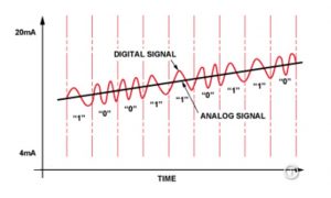
Design basics:HART provides value-added information about device and it’s diagnostic in digital form while retaining compatibility with 4-20 mA standard current loop automation architectures. As it consists of analogue and digital communication, HART is also called as a hybrid protocol. The digital information is carried by a low-level modulation superimposed on the standard 4-20 mA current loop. The digital signal does not affect the analogue reading because it’s removed from the analogue signal by standard filtering techniques.
HART digital communication signal is superimposed on analogue 4-20mA signal as below:
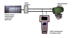
HART is principally a master/slave protocol which means that a field (slave) device speaks only when request received by a master. Two masters (primary and secondary) can communicate with slave devices in a HART network. Secondary masters, such as handheld communicators, can be connected almost anywhere on the network and communicate with field devices for calibration or diagnostic information purpose without disturbing communication with the primary master. A primary master is typically a DCS, PLC, or computer based central control or monitoring system.
A typical HART loop consists of:
-
Devices having HART output
-
Shielded pair cable
-
HART communicator (a tool to configure device remotely)
-
HART management software with computer (a tool to configure device from control room if required by client)
Application:Due to value added device diagnostic information/calibration facility and authentic 4-20mA current loop, HART protocol is most commonly used protocol in the process plants.HART protocol saves time and resources while troubleshooting and maintaining the plant. It provides easy start-up and commissioning of the plant.
c. DeviceNet:
Origin:DeviceNet was originally developed by American company Allen-Bradley in 1990 (now owned by Rockwell Automation). It is an application layer protocol on top of the CAN (Controller Area Network) technology, developed by Bosch.
Physical layer:The data is transported via two pair cables with the help of gateways, repeaters as required.
Transmission media:Transmission media is shielded, twisted two pair cable (one pair for 24V power and the other pair for communication).There are 4 types of standard DeviceNet cables: thick, medium, thin and flat.
Network topology:DeviceNet generally uses a Bus type of network topology.
Design basics: In DeviceNet communication protocol, the cyclic as well as non-cyclic data is communicated. Cyclic data is the data sent periodically from the devices like sensors and actuators related to process control to the controller.Non-cyclic data is the data sent by the devices for device configuration and diagnostics as requested by the master.
Devicenet has High network current capacity. A DeviceNet network may have up to 64 devices, with one device on each node addressed from 0 to 63.Thick or thin cable may be used for trunk lines or drop lines. The distance between network lengths varies with the data rate and cable length as per table below.
RATE DATA |
125 Kbps |
250 Kbps |
500 Kbps |
Length of main bus with thick-trunk cable |
500 m |
250 m |
100 m |
Length of main bus with thin-trunk cable |
100 m |
100 m |
100 m |
Maximum length of a main bus maximum-drop |
6 m |
6 m |
6 m |
Accumulated length of a main bus cumulative-drop |
156 m |
78 m |
39 m |
A typical Devicenet segment consists of:
-
Devices having Devicenet output/input
-
Devicenet cable with required mating connectors
-
Terminating resistors
-
Suitable Power supplies, gateways/converters, repeaters as required
Application:DeviceNet is generally used between industrial controllers and simple I/O devices like sensors, actuators.
d. ASIBUS:
Origin:The AS-Interface specification is developed by AS-International, a member funded non-profit organization located in Germany in 1994.
Physical layer:The data is transported via 2-wire cable with the help of gateways, repeaters as required.
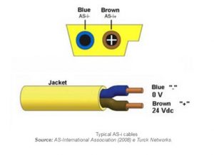
Transmission media:ASIBUS network cable is unshielded 2-wire cable. The standard ASI cable available in the market is flexible, flat cable which is suitable to be used in non-hazardous area in open cable tray.
Network topology:Any type of network topology i.e. Bus, star or ring is used in ASIBUS.
Design basics:ASIBUS (Actuator Sensor Interface Bus) is an industrial networking protocol used for connecting simple field I/O devices (e.g. binary ON/OFF devices such as actuators, sensors, rotary encoders, push buttons, and valve position sensors).
AS-Interface is an ‘open’ technology and is compatible with all common fieldbus systems. It is based on master/slave principle. Unlike Profibus /Fieldbus networks, the AS-I network does not require equipment description files and terminating resistors.
On ASIBUS, maximum 31 devices (max. 248 digital inputs / outputs)can be connected on one bus. Each device can have 4 digital inputs and 4 digital outputs. Maximum length of the line segment is 100 mtrs and can be extended to 300 mtrs with the help of repeaters. The bus voltage is up to 26 to 31 VDC and separate power supply is required for ASI Master or repeater.
Typical ASI black flat cable is used to power ASI master/repeaters.
Transmission rate of ASIBUS is 167 Kbits/s.
A typical ASIBUS segment consists of:
-
Devices having ASIBUS Output/Input
-
ASIBUS cable with required mating connectors
-
Suitable Power supplies, gateways/converters, repeaters as required
The below picture shows typical ASIBUS segment:
Application:ASIBUS is generally used between controllers and simple I/O devices like sensors, actuators.
-
PROFIBUS:
Origin: Profibus technology was introduced in the early 1990s.The PROFIBUS DP and PROFIBUS PA technologies are specified in the international standards EN 50170 and IEC 61158.
Physical layer:The data is transported via pair cablewith the help of couplers, gateways, repeaters as required. For Profibus DP, physical layer is as per RS-485 & IEC 61158 standards. For Profibus PA, physical layer is as per IEC 61158 standard.
Transmission media:Twisted pair, shielded(Type A) cable is generally used for Profibus communication.
Network topology:Any type of network topology i.e. Bus, star or ring is used in Profibus.
Design basics:PROFIBUS is a standardized, open communications system for all areas of application in factory and process automation. There are two types of Profibus protocols: Profibus DP and Profibus PA.
PROFIBUS DP (Decentral Periphery) is generally used for electrical; sensor interface .It is also used between controller and I/O cards. There are three versions-DP-V0, DP-V1 and DP-V2 available in Profibus. Out of these, most commonly preferred is DP-V1& DP-V2. DP-V1 is for acyclic and cyclic data exchange and alarm handling. DP-V2 is for isochronous mode (i.e. data exchange at equal time interval).Transmission rate of Profibus DP is upto 12 Mbit/s. On Profibus DP max.126 devices can be connected with repeater and max. length 1200m can be covered with type A cable (it can go up to several kilometers with fiber optics).
PROFIBUS PA (Process Automation) is an extension of PROFIBUS DP developed to cater the requirements of process automation. PROFIBUS PA uses DP-V1 protocol for communication at field level. Transmission rate of Profibus PA is up to 31.25 k bit/s. On Profibus PA max. length 1200m can be covered in non-hazardous area and 1000m can be covered in hazardous area with type A cable (total length of segment=length of the trunk+length of all connected spurs).
The total no. of devices connected on Profibus is a function of total data value to be transmitted by device, current capacity of segment coupler,voltage requirement at each node, data transmitting capacity of Profibus masters/link, length limitations etc. Generally, as an average maximum 6 nos. of devices are connected on one Profibus segment in hazardous area with type A cable and max.15 nos. of devices are connected on one segment in non-hazardous area with type A cable.
PROFIBUS system requires a data description file of the device i.e. output data, input data,data format and supported transmission rate, so that it can integrate the field devices into the bus system.
A typical Profibus segment consists of:
-
Profibus compatible I/O cards
-
Devices having Profibus Output/Input
-
Type A cable with required mating connectors
-
Terminating resistors
-
Suitable Profibus couplers/links, repeaters as required
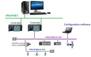
The below picture shows typical Profibus architecture:
Application:Profibus DP is used between controllers and I/O cards/RTUs; it is also used for sensor actuator /electrical interface applications. Some field instruments are available with Profibus DP output only because of high power consumption. Profibus PA communication is generally used between the controllers and analogue I/O devices in process plants.
f. FOUNDATION FIELDBUS:
Origin:This open architecture is developed by Fieldbus Foundation based on IEC-61158 during 1995-1998.
Physical layer:The data is transported via shielded, pair cable with the help of gateways, repeaters as required. The physical layer conforms to ISA SP50.02 and IEC 1158-2 standards for fieldbuses.
Transmission media:Twisted pair, shielded (Type A) cable is generally used for Fieldbus communication.
Network topology:Any type of network topology i.e. Bus, star or ring is used in Fieldbus.
Design basics:
Foundation Fieldbus is an all-digital, serial, two-way communications system that serves as the base-level network in a plant or factory automation environment.
There are two related implementations of Foundation fieldbus have been introduced to meet different needs within the process automation environment. These two implementations use different physical media and communication speeds.
-
FoundationFieldbus H1 – Operates at 31.25 Kbit/s and is generally used to connect to field devices and host systems. It provides communication and power over standard stranded twisted-pair wiring in both conventional and intrinsic safety applications. H1 is currently the most common implementation.
-
HSE(High-speed Ethernet) – Operates at 100/1000 Mbit/s and generally connects input/output subsystems, host systems, linking devices and gateways.
The communication method of fieldbus is client /server. The length of the fieldbus is determined by the communication rate, cable type, voltage required at last node. However maximum distance covered by H1 segment is 1900 mtrs and by HSE segment it is 100 mtrs.The permissible data size depends upon the card used,according to Fieldbus standard; it can transmit or receive 246 bytes.
The total no. of devices connected on Fieldbus-H1 network is a function of total data value to be transmitted by device, current capacity of H1 card, Minimum operating voltage requirement at last node, data transmitting capacity of gateway/I/O cards, length limitations etc. Generally, as an average maximum 6 nos. of devices are connected on one Fieldbus segment in hazardous area with type A cable and max.15 nos. of devices are connected on one segment in non-hazardous area with type A cable.
A typical Fieldbus segment consists of:
-
Fieldbus compatible I/O cards
-
Devices having Fieldbus output/input
-
Type A cable with required mating connectors
-
Terminating resistors
-
Suitable H1 cards, linking devices/ gateways, power supplies, repeaters as required
There are four types of cable can be used for Fieldbus. Type A cable is the most preferred for new installations because it allows for the most versatile lengths. The other types of cable are for installations where cable already exists from 4-20 mA systems. See below table:
Cable type |
Description |
Size |
Max. length |
A |
Shielded, Twisted pair |
#18 AWG (0.8mm2) |
1900 m |
B |
Multiple –Twisted –Pair with shield |
#22 AWG (0.32mm2) |
1200 m |
C |
Multiple –Twisted pair without shield |
#26 AWG (0.13mm2) |
400 m |
D |
Multi-core , w/o twisted pairs and having overall shield |
#16 AWG (1.25mm2) |
200 m |
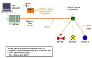
Typical fieldbus H1 network segment is as below:
Foundation fieldbus system requires a data description file of the device so that it can integrate the field devices into the bus system.
Application:
Foundation fieldbus technology is mostly used in process industries.
g. Overall comparison of communication protocols:

comparison
-
Wireless network:
The establishment of wireless technology for entire solutions is still in progress.Currently wireless applications are available for monitoring. In the near future, wireless solutions for safety shut down systems, for total control and complex applications may be available.
The ISA100 committee of the Instrument Society of Automation is responsible for the standardization and generation of guidelines for the implementation of wireless devices and systems for industrial applications.
Some manufacturers also follow Wireless HART protocol which is registered under IEC-62591. IEC-62591 standard specifies guidelines for Industrial networks, Wireless communication network and WirelessHART.
WirelessHART uses a 2.4 GHz frequency band which is license-free and used worldwideas a transfer medium for several radio technologies, including WLAN, Bluetooth etc.
For security purpose, every network has a unique network ID and join key before a device can join the network. This join key can be common for each device on the network or it can be unique to each device, creating an Access Control List (ACL).
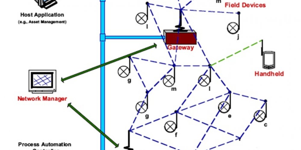
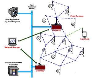
WirelessHART uses a flat mesh network where all radio stations (field devices) form a network. Every participating station serves simultaneously as a signal source and a repeater. The original transmitter sends a message to its nearest neighbour, which passes the message on until the message reaches the base station and the actual receiver. In addition, alternative routes are set up in the initialization phase.
If the message cannot be transmitted on a particular path, due to an obstacle or a defective receiver, the message is automatically passed to an alternative route. So, in addition to extending the range of the network, the flat mesh network provides redundant communication routes to increase reliability.
Like traditional HART concept, WirelessHART devices contain similar or a subset of all of the diagnostics of wired HART devices.Diagnostics information is available through
HART commands as well as accessible throughDevice Descriptions (DD) either locally through a field communicator or remotely using asset management software.
Typical wireless mesh network is as below:
While designing wireless solutions, it needs to study functional, operational and infrastructure requirements. This includes study of design stage layouts, site visits in order to identify the mapping of the field devices, required nos. of wireless gateways/repeaters/adapters and it’s locations with respect to physical obstacles, estimation of the cable length between the gateway and the system interface device etc.
For wireless field devices along with other required technical specifications, the specifications related to wireless communication such as device battery life (based on the maintenance requirements and the remote location if any, hazardous area class), update rates in seconds, communication type i.e. ISA-100 or IEC-62591 need to be included. In case of WirelessHART, requirement of WirelessHART handheld communicator need to be consider to configure the devices.
The control system related wireless specific software requirements, communication, redundancy, spare, expansion requirements also needs to be identified in early stage.
-
Engineering approach:
In Oil and Gas industry such as in Refinery and Petrochemical industries, the processes and controls are highly complex. Due to optimized energy/resources, need of ecologically sustainable developments, environmental performance of the plant and competitive globalized economy, these processes have become more complex.
The increasing complexity of the process industry production systems demand the fast and reliable process and condition monitoring, supervision, integrated diagnosis and suitable communication technologies to achieve the synergy among all different subsystems and therefore increase plant performance, energy optimization, reliability ,safety, sustainable developments and global competitiveness. Due to these requirements, a typical oil refinery invests millions of dollars in the plant control system. It becomes prime responsibility of engineering while selecting the suitable control system with right communication protocols to cater the need of the plant.
Hence during engineering, the below factors are need to be considered while selecting the suitable control system with correct communication protocols from various options:
-
Application of the control system i.e. whether it is for shut down, process plant, packages, Fire and Gas, safety etc.
-
Study of existing control systems if any in the plant – Need of communication and communication compatibility with new control systems etc.
-
The distances between various control systems/various interfaces.
-
The type of data to be transferred between various distributed control systems i.e. critical / non-critical, type of Inputs /Outputs.
-
Communication compatibility between various control systems available in the market.
-
Control system services available based on the geographical location of the plant.
-
Integration with Plant management, Asset management systems if any.
-
Maintenance/Diagnostic requirements and availability of skilled resources for the smooth plant operation.
-
Required speed of the communication protocol based on the type of processes.
-
Software and hardware requirements etc.
The selection process highly recommends the close interaction with plant owner/client for their requirements and available resources/factors. This will ensure the more appropriate selection of the control system communication protocols required in the plant.
Conclusion:
All these open communication protocols can help plant owners to obtain the plant absolute status any time very easily, it reduces maintenance cost and unplanned shut downs and helps to increase production volume. The plant owners shall come forward for value added, latest communications technologies for better process control & management and to encourage the further technological advancements.
Bibliography: 
Books and references from:
-
Guidelines for planning and commissioning PROFIBUS DP/PA by Endress+Hauser
-
System engineering guidelines by Fieldbus Foundation
-
Modicon Modbus Protocol Reference Guide PI–MBUS–300 Rev. J
-
DeviceNet Media Design and installation guide by Rockwell Automation
